
CIMDIT part 2, the electronics
As mentioned in part 1, I have 4 modules, the brain, a key matrix modules for up to 64 buttons, the analog input module and a module for rotary encoders.
Lets describe them part by part.
The brain
The core is the Arduino Pro Micro as it provides the USB-Connection. Basically it's just the module and a bunch of connectors.
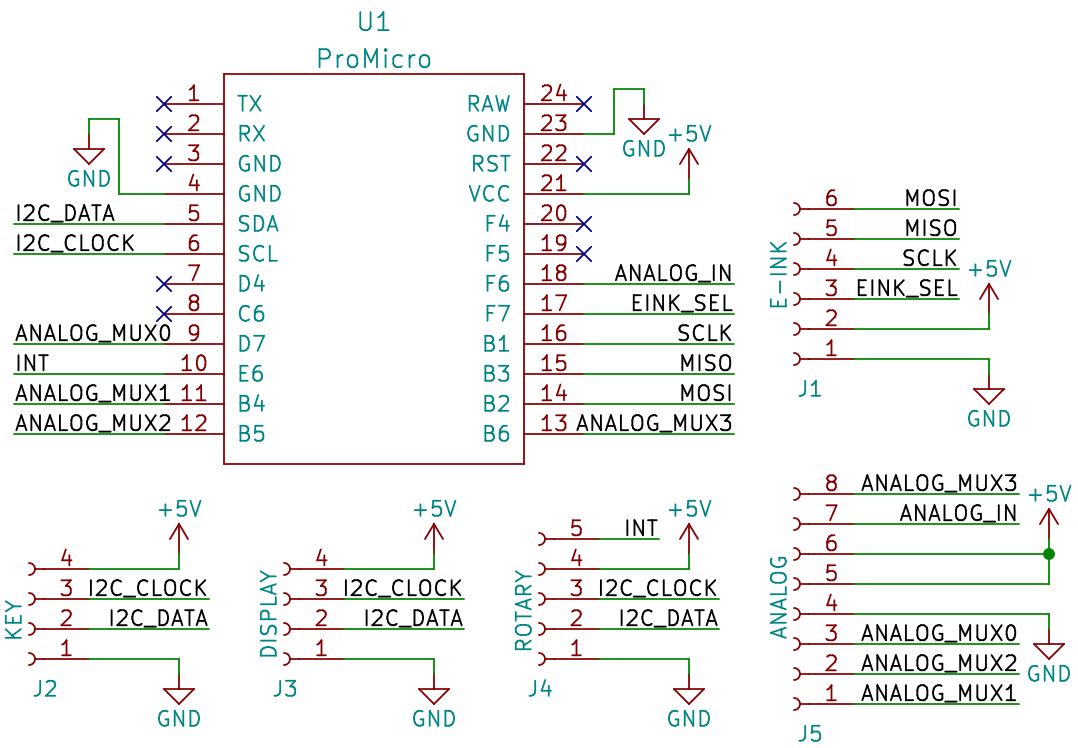
The connector pins are ordered so that routing makes it easier. Full layout for building on perfboard later.
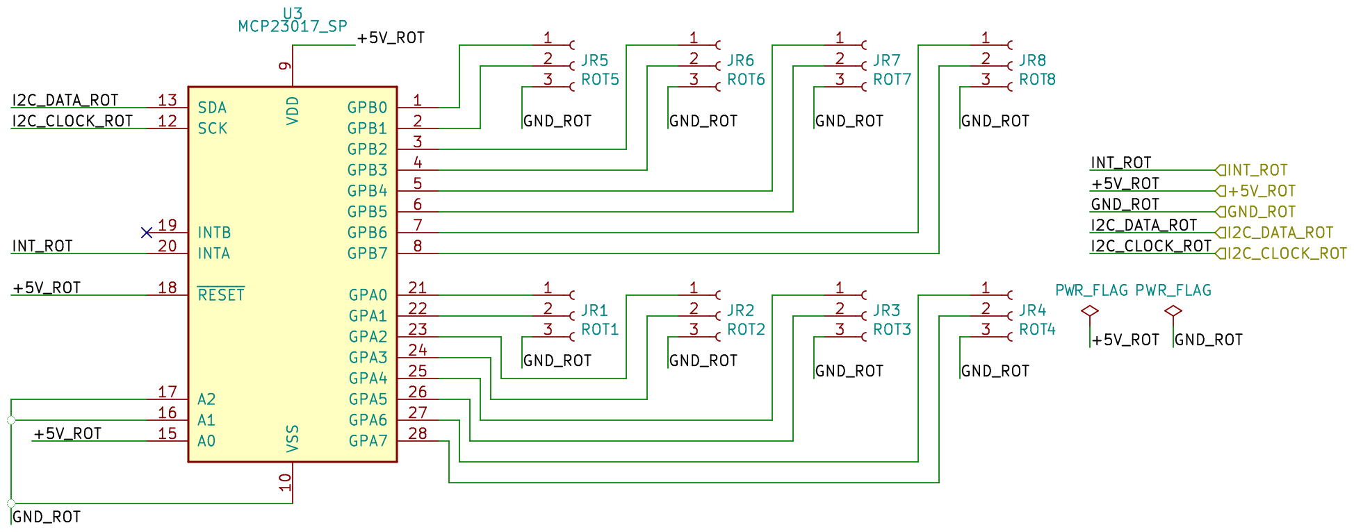
Rotary encoder board
Equally impressive and complicated is the rotary encoder board:
Analog Multiplexer Board
The multiplexer board is just a CD74HC4067 breakout board.
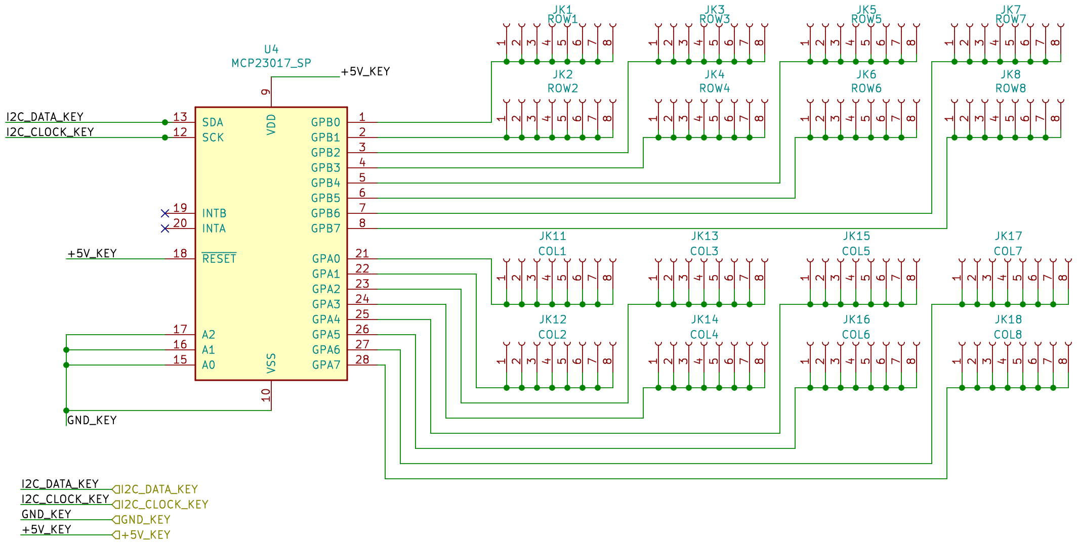
The key matrix
This board is finally a bit more challenging. First I'd like to explain what a key matrix actually is.
Normally you are used to connecting one switch to a digital input. This is fine for a few inputs, but like 64, it gets complicated.
Take a look at this animation: By Kai Burghardt - Own work, CC BY-SA 3.0, https://commons.wikimedia.org/w/index.php?curid=28944795
When your micro controller powers one of the rows, let's say row0 and reads the values from the columns you can see which buttons are pressed on the given row. By changing the row another set of keys can be read. This is one version of the keyboard matrix.
But there is an issue. If you press multiple buttons at the same time it can result in ghost buttons because things are getting connected through multiple switches. To fix this you need to add diodes to one pin of the switch so that current can not go through "the wrong way".
You can use above schematic as long as you solder in the diodes on the wire from switch to board or use this circuit which includes the diodes: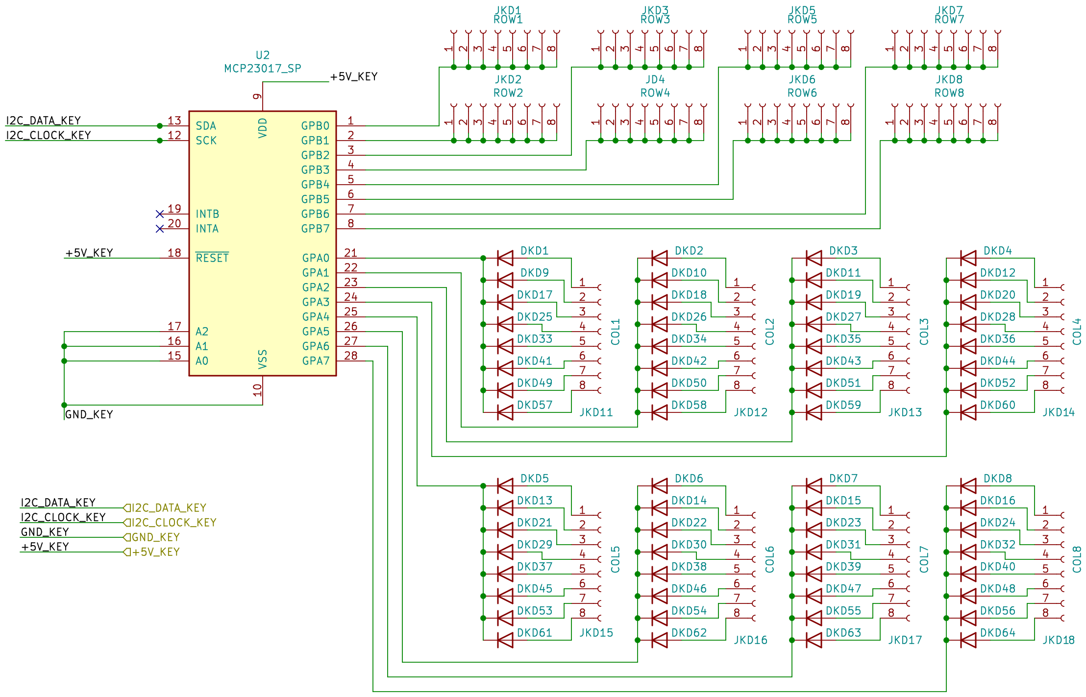
PCB layouts
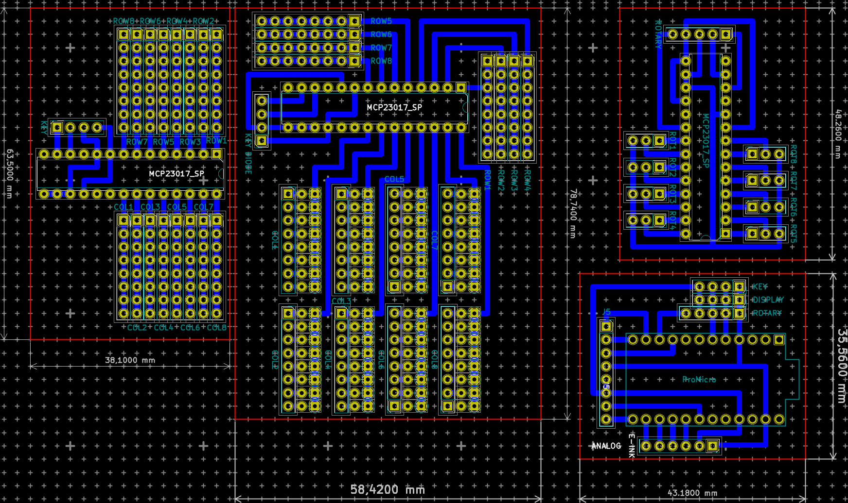
From left to right:
- Key matrix with diodes in the wire
- Key matrix with diodes on the board
- right top: the rotary encoder board in 8 encoder configuration
- right bottom: the main board
The diodes on the board are mounted vertically to save space, this looks like this: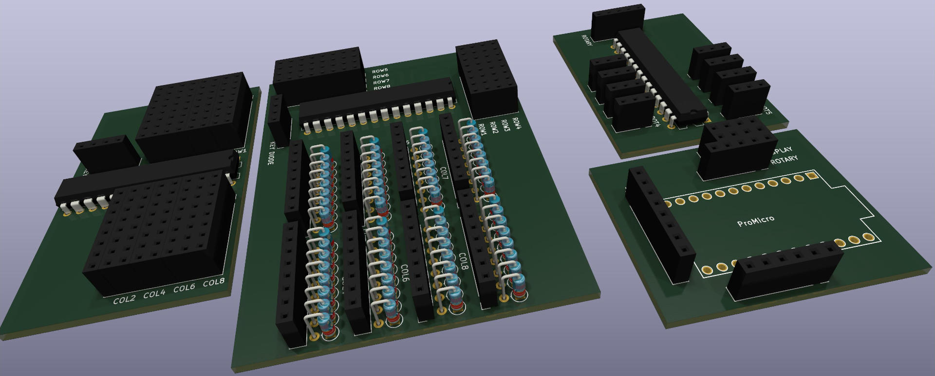
The PCB design is specially made to be build on the normal perf board, no need for creating custom PCB.
The electronics (KiCad Version 6) as well as future software and 3D-Plans are available on our git repo.
Update 2022-02-18. The PCBs have been build an tested, one small bug was found. The Enable pin for the analog multiplexer needs to be pulled down, not up. Also the PCB has been shrunk a tiny bit. Updated schematics and PCB in the git repo.
Update 2022-03-22. I also added more compact versions of the rotary encoder and key matrix (with diodes in the wires). The functionality is still the same.
The next part will handle parts of the software side, this will get more complicated.