Using the Path Animator tool in Blender
Let me start with a disclaimer, I'm a noob when it comes to Blender.
I get around, but I'm not an experienced user. And no, I did not create my donuts yet, and try to skip this if possible ;)
To recap what this is about: this tutorial will be part of the following short animation (show in full screen mode):
Modelling
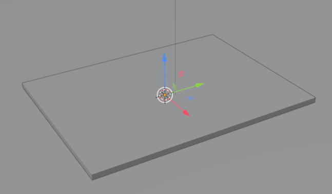
The first step you need is a basic plane, box or other object that you want to modify with the animation.
Since I want to do the circuit board, I'll use the dimensions of the physical object scaled by a factor of 1000. I found that Blender becomes hard to use with object in the scale of a few mm. So 50m x 66.7m x 1.6m instead of mm. Also move it up by 1/2 of the height.
And for better contrast, I'll add a large plane at height 0 to cover my view.
So this is my modelling completed (yes, totally exciting):
Texture mapping and Object preparation
For the floor I use a predefined Material from the "Material: Material Library" plugin called woodP with the default settings. Feel free to get creative here. The Cube (our circuit board) gets a generic brown material on the object, but a different material on the top. This material on the top is where the magic will happen. It will use a displacement map, so to make it work you need to setup the rendering. I switched the rending engine to Cycles and enabled the experimental Features Set. This allow to enable the "Adaptive Subdivision" in the Subdivision Modifier. So let's add this given Modifier to the cube and enable the "Adaptive Subdivision" options and switch to Simple mode. For now, nothing has changed in the view, but it will happen soon.
Let's start with the UV mapping for the top, it need to be adjusted a bit. Got to the material for the top and add a Texture node to the Base Color Input. I used the circuit board export (the path traces):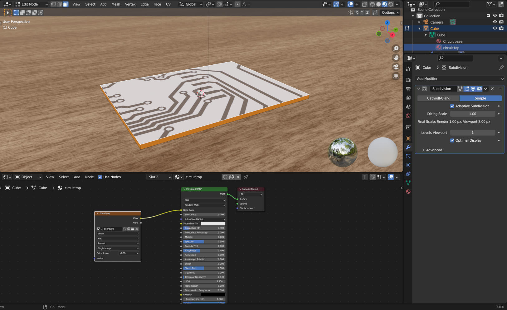
You can see, the texture does not sit right on the top face.
So, switch to the UV editing of the top and drag the corners to the corners of the texture. The texture should fill the entire face.
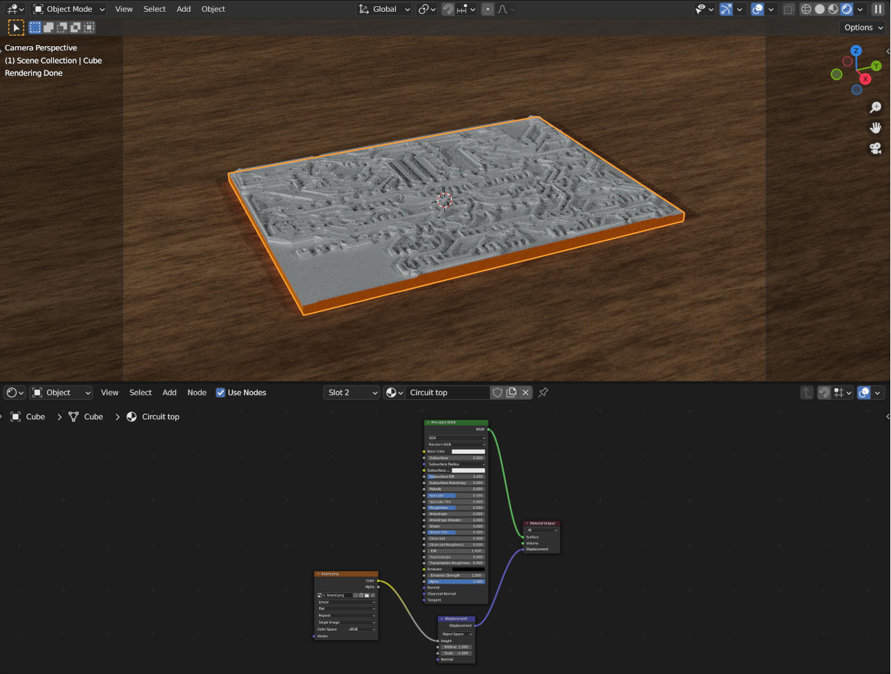
And to test if the displacement works, go to the material tab on your cube, expand settings and surface and change Displacement to "Displacement and Bump", go to your material node view and move the texture to the displacement input and insert the Vector->Displacement node in the path with the texture in the height input. I set the scale of the Displacement to -1 and the Height to 1 to make it look right, the copper traces are above the board material.
To make the lighting a bit more interesting, remove the default light and add an environmental texture in the "World properties" tab and used an image for the color. I picked studio.exr that came with Blender.
Your project should look like this:
The magic
Now, while the picture is neat, that is not the reason for the tutorial, now let's enter the interesting part.
Use the used image to create the "fancy" texture for the animation. If you have not downloaded the tool yet, right click and save as html somewhere. Open the file in a browser. If you want to use the same image as I did, download it as well.
In the tool, adjust the setting to get to the desired effect. If you use the example, these are
Weight of the path: 1
Weight of the block: 100
Threshold: 254
Maximum Distance: 10000
Start: 472,600
Let it run and save the output.
Let's start with the basic path, the "removal" of the unneeded copper.
Replace the existing texture with new generate one. It should look a bit odd for now. To fix this, we only want to blue channel, so insert the "Converter->Separate RGB" node in the path between the texture and the displacement node and move the output to the b channel. Now it should look like it did before.
If you use the C++ version you can skip this, but for the JS version you need to combine the red and blue channels.
To do this, add a "Converter->Math" node on the red channel, set to multiply and set second input to 255 and first input to the r channel of the texture. This results in an image with the range of 0 to 255.
The magic part is a revealed by the called "Converter->Math" node. Insert this into the path from the splitter (or last math from above) to the displacement. Change the function to "less than". The If you move the threshold from 0 to 255 (or from 0 to 1 in the C++ version), you'll see the lower parts slowly carved in. 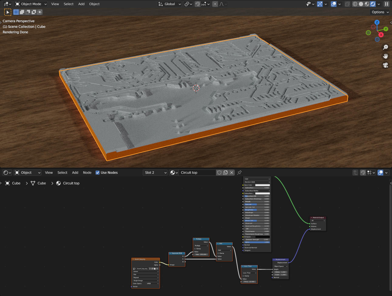
But the some areas are set to the low point where we actually want to see them high. This needs fixing. The blue channel to the rescue!
If we add another Math node between the last multiply and the displacement node and use the b channel from the rgb splitter, only the animated parts will be used for the displacement. Goal reached. If you get a slight indent where the should be none, change the texture interpolation to "Closest". That should get rid of it.
This is the displacement part done. For more realistic output reduce the scale of the displacement to something you like, like -0.1.
But wait, this is not how the exampled looked like.
Right, this needs extra steps.
Material change
The easiest way is to change the base color of the top material based on the "reveal" status. This can be done with the "Color->MixRGB" Node. Pick two colors and connect the output of our last multiply to the Fac input, but leave the old connection intact. I used "0013FF" for the color 1 and "001281" for color 2. I also added a silk screen (white print on top) by adding a texture with a MixRGB Node on input 2 and set to screen with fac set to 1 to mi this in.
The almost final result looks like this:
The "laser effect"
With the given steps so far you might have an idea how to do the "laser effect". In case you don't have the idea yet follow theses steps.
Add a "Input->Value" Node and use the output for the Threshold value of the "Less Than" node. We need to use it multiple times, so extracting it makes animation easier.
Add another "Converter->Math" node, and set to "Compare". Connect the output of the node to the shader "Emission Strengh" input and pick a color. I used #FF8600. Use the output of the add node as input 1 and the value of the input node as value 2. Choose an Epsilon for the compare as you like. If you move the input value you should see the revealing path and the changing area should be lighting up. You could limit it to only show the "to be revealed" area, use multiple colors, gradients or whatever you like. This is beyond this tutorial. In a quick animation, nobody will notice those details.
Animating
Now you can create the animation by changing the input value (the threshold) from 0 to 255 over a period of key frames.
For the quick preview, the Eevee render is good enough, but you don't get the displacement effect, but the result are there in way less time.
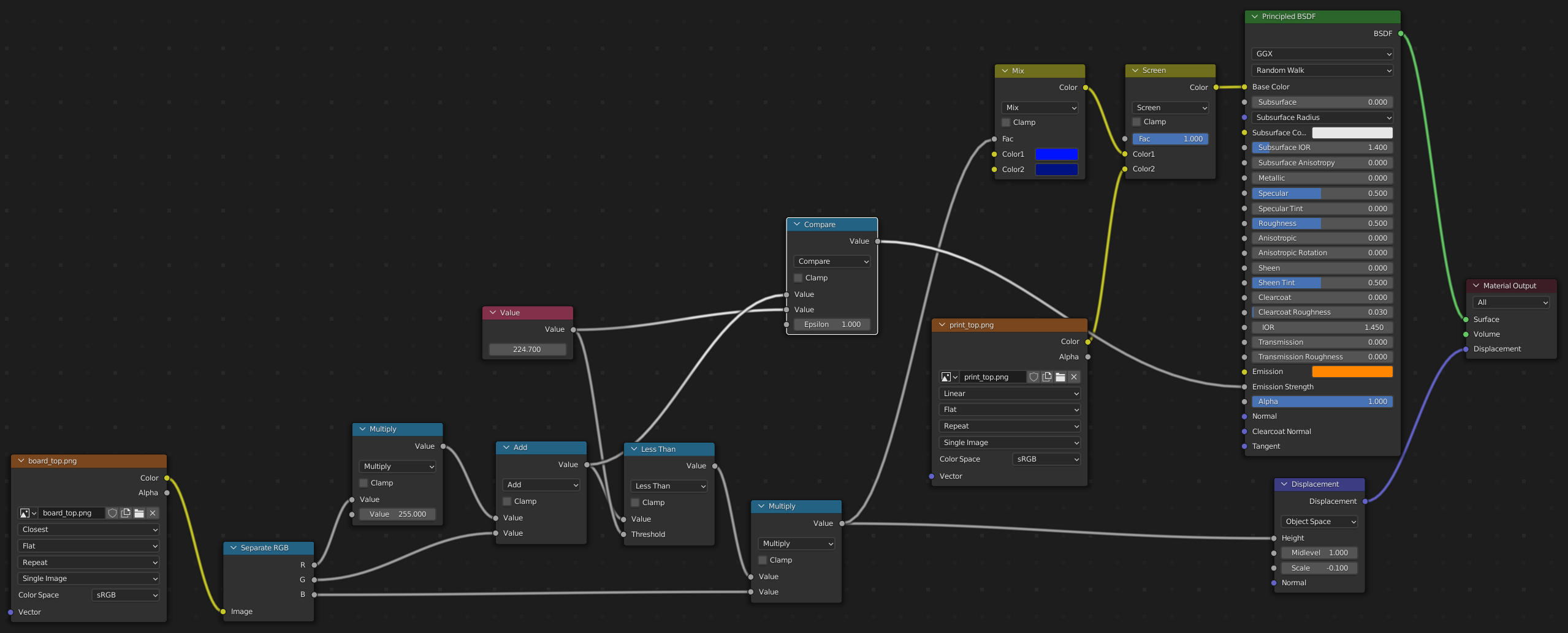
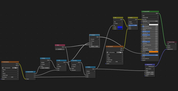
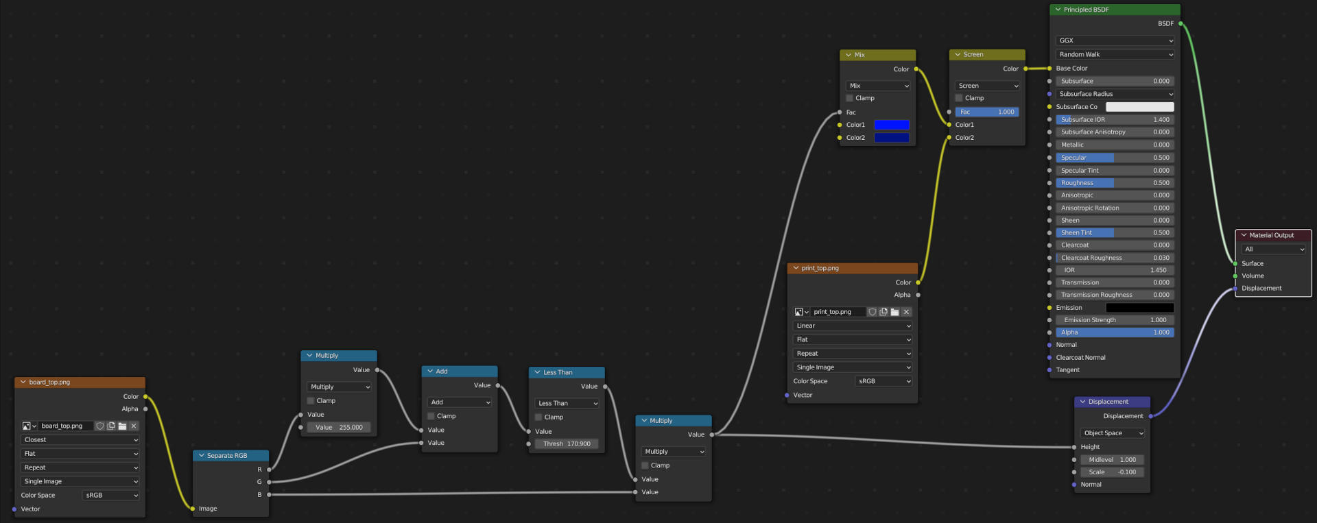
TL;DR
Here is the final shader config: