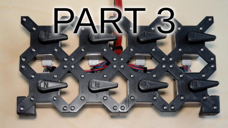
Play "Music" with stepper motors Part 3
This is part 3 of the mini series. Please read part 1 and part 2 before this.
The tricky part is to control the stepper motors based on the desired frequency and also doing this with 8 channels.
Those parts are dealt with in the Midi2Stepper class.
To speed up some things I split the variables for each channels into an dedicated variable and not using array.
This saves a few clock cycles and they are rare here.
The begin() function enables the output pins and sets their default values. Nothing interesting.
  // set stepper pins to 0 and enable output
  for (uint8_t i = 0; i < 8; ++i) {
      digitalWrite(i+5, false);
      pinMode(i+5, OUTPUT);
  }
  // set /enable pin to 1 (off)
  digitalWrite(13, true);
  pinMode(13, OUTPUT);
The interesting part follows. We are using the internal interrupt to trigger to step impulses to the controllers.
To do this, we configure the internal timer 1 to call our interrupt function 48000 times per second. This value
results in the most accurate representation of our used frequency range.
Basically you tell the timer: no pre-scaler, and every 335 clock cycles. Why 335?
Following this math: ( 16(MHz) / 48000(calls/second) ) - 1. Which is 16.000.000 / 48.000 - 1 = 332.
But that's not 335. Correct. The 335 is adjusted to the actual measured output frequency and this might differ
from chip to chip or by temperature. But in the end, you won't hear the difference.
As a consequence this shows us that our inner interrupt function may only use ~300 clock cycles. And this is
a tricky thing to do.
  cli(); // disable interrupts
  TCCR1A = 0;    // Set the CTC mode
  TCCR1B = 0;
  TCNT1 = 0;
  OCR1A = 335;  // 333 = (16*10^6) / (480000*1) - 1 (must be <65536), adjusted to actual measured frequency
  TCCR1B |= (1 << WGM12);
  sei();  // enable interrupt
The power function is boring, it enables or disables the interrupt and sets the output pins.
Now to the main interrupt function, the tricky bit.
ISR(TIMER1_COMPA_vect) {  // timer1 interrupt 48kHz
  m2s.tick();
}

void Midi2Stepper::tick() {
  bool bmod = false; // was port b modified
  bool dmod = false; // was port d modified
  // create local copies to speed things up
  uint8_t portb = PORTB;
  uint8_t portd = PORTD;
  uint8_t enable = m_enable;
first we keep track if the b or d port would be modified and we save a local copy. This is technically a race condition, but nobody else modifies the ports.
  // for each
  if (enable & 1) {
    ++m_counterA;
    if (m_counterA > m_cEndA) {
      portd ^= (1 << PD5);  // toggle D5
      dmod = true;
      m_counterA = 0;
    }
  }
This code is repeated 8 times, for each output. Yes, a for loop and some non-code-duplication might be better to read, but remember the ~ 330 clock cycle limitation.
if the enable bit for the given output is set, increase the counter for the channel.
If the counter reaches or exceeds the threshold, we toggle the right pin on the right port. We also note that the port was modified and we reset the counter.
The >= is needed, because the loop function could have set this to a lower value in the mean time.
if (bmod)
    PORTB = portb;
  if (dmod)
    PORTD = portd;
Finally we set the output port if it was modified.
Not using the output port directly gives our compile the option to keep the portb or portd variable in a register instead of going to the (slow) RAM. Again, counting
instruction cycles here.
The final and also boring function is the setChannel. It just sets the end counters used in the interrupt function.
void Midi2Stepper::setChannel(uint8_t channelNum, uint16_t freq) {
  uint16_t v = 0xFFFF;
  if (freq > 0) {                        // was a frequency set?
    v = (((uint16_t)24000) / freq) - 1;
    // channel is turned on later
  } else {
    m_enable &= ~(1 << channelNum);      // turn off specified channel
    digitalWrite(5 + channelNum, false); // set output pin to 0
  }
  switch (channelNum) {
    case 0:
     m_cEndA = v;
     break;
...
   case 7:
     m_cEndH = v;
     break;
  }
  if (freq > 0) {                        // was a frequency set?
    m_enable |= 1 << channelNum;         // turn on specified channel
  }
}
First, we calculate the new counter with the terrible complicate formula (24000/freq) - 1) or we turn the channel off.
Why 24000 and not the 48000 from above? Simple: to output a frequency of 1000Hz you need to toggle the output twice,
0 to 1 after 0.5ms and from 1 to 0 after 1ms. So twice as often a the frequency. This is also the reason for the 48kHz interrupt calls.
We could create up to 24kHz audio, you won't be able to hear this, but you could. Also this gives the above mentioned closer
matching to the desired frequencies.
Then the right counter is set and finally the channel is enabled. If it already was enabled, no change.
If we don't disable the channel before we set the new value, the stepper might keep turning for another interrupt cycle.
Not a huge problem.
The full code can be fetched on our new git repository at https://git.contentnation.net/grumpydevelop/midi2stepper
If you want to, feel free to experiment with it, you could reduce the maximum frequency and expand the system to more stepper motors,
but 8 are already a lot ;)
If there is interest in it, I have an idea for a version with more or less unlimited amount of steppers. Just get in contact.
