
CIMDIT part 4: Profiles
If you haven't read the first three parts, please go ahead and read them. Part 1 Part 2 Part 3.
To summary, I'm creating a 3D Mouse, a macro keyboard and a gaming joystick in one item using a single Arduino Pro Mini (clone) with 32kB Flash, 2,5kB RAM and one external 32kB EEPROM (AT24C256) that supports up to 64 buttons, 8 rotary axis and up to 16 analog input, multiple profiles that can be switched on the fly, a small 128x32 OLED display and a possibility to have applications show stuff on the OLED screen via serial command line.
And, of course, the profiles can be changed on runtime without reprogramming any code, including optional profile icons (until the flash is full).
And oh boy, this "Completely Insane Multi Device Input Thingy" got extremely insane.
I created a 3Dprinted case that houses 5 rotary encoders, the joystick, one analog slider and 26 buttons, the ones used in mechanical keyboards.
It is available in the git repo as a FreeCAD file, but to be honest, use those buttons that just need a round hole and buy a plastic case in 200x120x55mm for less than 13 Euro, drill the needed holes in it and be fine. Or spend another few hours to optimize my design and let it print for a few hours ;)
I already spent way too much time with it.
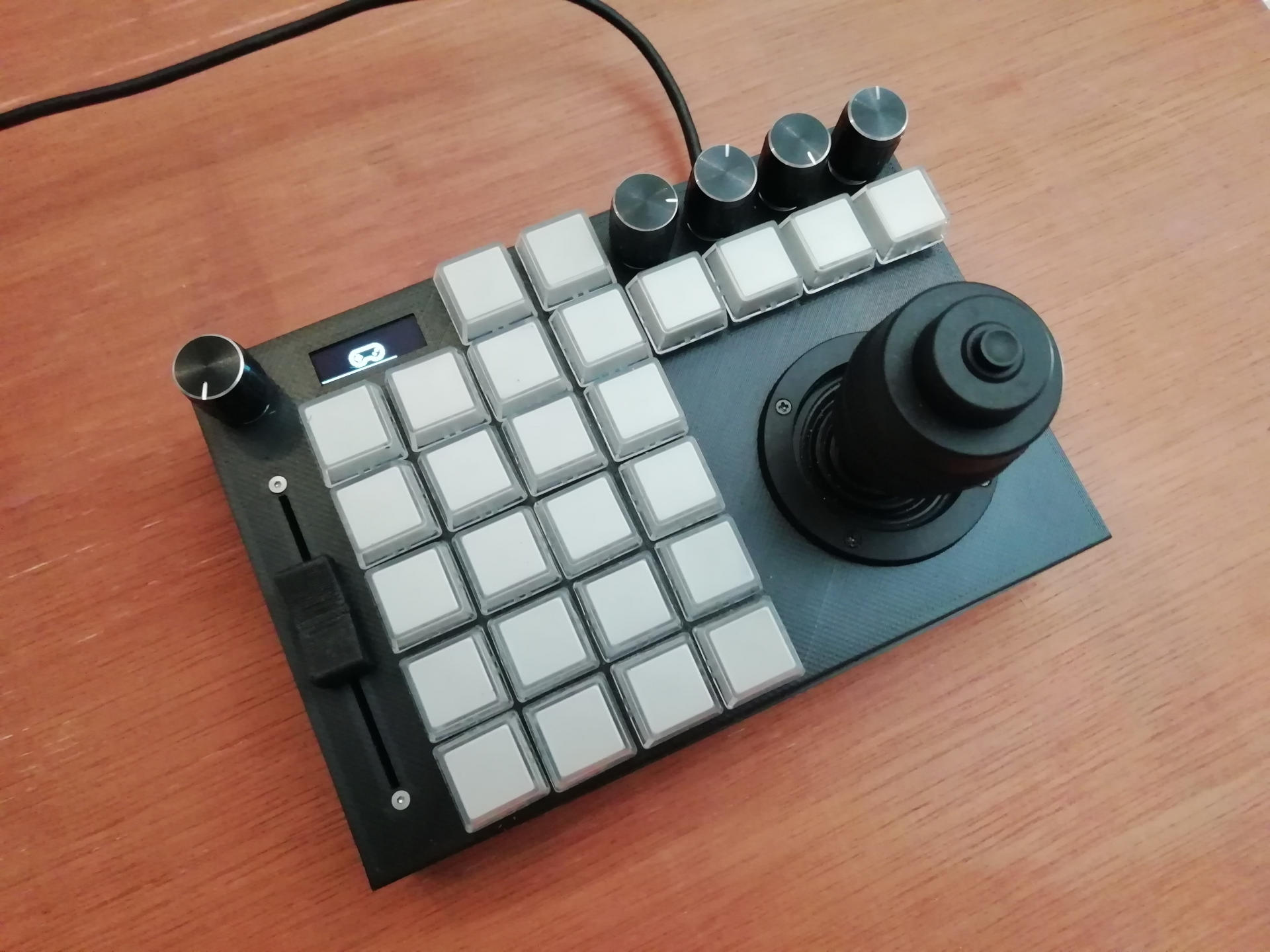
This also shows the custom profile icon here a game pad (hard to see on the photo) for the gaming/joystick profile. It totally makes sense to define one for your special game, use another icon for that.
Speaking about spending way too much time...
The next insane part: Make it actually work
Or how to squeeze too much functionality into a 32kB Arduino.
Spoiler ahead, in the current version I use 26660 Bytes (92%) of the available 28672.
I was at over 40kB at one point...
External Libraries
Let's start with the external libraries you need
I'm using
- the HID-Project by Nico Hood (newest Version 2.8.2, installed via library manager)
- the Adafruit MCP23017 Arduino Library (newest Version 2.1.0 installed via library manager)
- glcdfont.c font file from the Adafruit GFX library as well as some character and vertical line drawing code based on it but heavy modified (more on that later)
I tried different versions of OLED libraries, but they all resulted in too large code, they aren't big, but I have too much other stuff in the flash.
This ended in writing my own custom software for driving the OLED screen and drawing library. I wrote most of it based on the datasheet of the SSD1306 controller and previous work I've done. It's not the first time I paint onto a byte or bit buffer ;) For full details, please "use the source, Luke" (kind of TM).
The code to communicate with the external EEPROM is also written from the datasheet, no external library (it's trivial).
Let's dig deeper into the code
The main sketch
Nothing substantial changed from the previous description, just some cleanup and I move the #defines into a separate file, because they get reused. As mentioned, I replaced the Arduino SSD1306 library with my own, the interface stayed mostly unchanged (from the user's point).
One extra feature in here is that the user can send commands via serial to the CIMDIT device.
To not trigger "accidents" when some tool is scanning the serial connections, like a 3D-Print-Slicer tool, all commands have to start with "cimdit:"
- "cimdit:d<timeout>" to display a graphics (monochrome, has to match your display in size) in a (ascii) pbm file format (a clear text file format, trivial to parse), you will be prompted with "ready for .pbm file". After that, just copy/paste/send the original pbm file. After the timeout has passed, the image will be removed.
- "cimdit:p<timeout>,text" to display shows given text for <timeout> seconds
- "cimdit:f" prints out profile configuration
- "cimdit:F<configuration>" saves and loads new configuration.
Instead of temporary debug out, now the profile class is called to do magic.
The HAL class
There are only minor bug fixes since the last article. I increased the scan rate, the keys felt sluggish.
The rotary class
No noteworthy change since last article.
The SSD1306 class
Depending on your knowledge about the I2C and bit level manipulation of graphics this is either trivial or insanely complex.
In the end there are a few graphics function that set or unset specific bits in a memory buffer. Since the OLED screen is monochrome,
each pixel is represented with a single bit, so the whole memory for the screen is 128x32 pixel (bits) or 128x32/8 = 512 bytes. That's a good chunk of our available 2500 Bytes of RAM. But we have (according to the Arduino IDE output) 1290 bytes left, so no issue.
To show the data on the screen you need to copy this memory content to the OLED. You can use display() for that or if you only want to update a partial screen (way faster) use displayPartial(part). The parameter part can be 0 (top quarter) up to 3(lowest quarter).
The profile class
This is where the magic (and the insanity) happens.
The current version supports up to 8 profiles, but this can be changed in the defines.h file.
But let's pause this for a moment and explain the profiles itself
The Profiles
To manage the profiles, there is a html file in the repo (profilegenerator/html/index.html or here save it locally) that you open in your browser. With this you can create your profile using JSON. It will generate the binary representation for you that you can upload via the mentioned serial command. This works fine in the Arduino IDE serial monitor as well. You really don't want to create the binary by hand.
The json consists of a list of profiles, so to start it with no profiles it is a mere "[]".
Example profiles will be added from time to time, but here are some starters.
A basic profile
Mandatory is a profile name, and not strictly mandatory, but useful, at least one mapped button, axis or rotary encoder.
Let's start with a base profile that should always be included:
{"name": "Your Name","mappedbuttons": [{"source": 62,"type": "SWITCH_PROFILE"}],"mappedaxis": [],"mappedrotary": [{"source": 0,"type": "PREV_PROFILE"},{"source": 1,"type": "NEXT_PROFILE"}],"macros": []}
This defines the name of the profile, one mapped button and 2 mapped rotary events.
Mapping buttons and rotary encoders
Each button has a button source, this is the button number that was pressed. Depending on the wiring, the number is different. My rotary encoder next to the display is button 62. type is the action you want to do, these can be:
- JOYSTICK_BUTTON (a button on the joystick output)
- MOUSE_BUTTON (a button on the mouse output)
- MOUSE_REL_X_AXIS (a relative mouse movement on the X axis)
- MOUSE_REL_Y_AXIS (a relative mouse movement on the Y axis)
- MOUSE_REL_WHEEL (a movement on the mouse wheel)
- NEXT_PROFILE (advance one profile)
- PREV_PROFILE (go back one profile)
- SWITCH_PROFILE (activate profile)
- MACRO_PRESS (a macro sequence on key press)
- MACRO_RELEASE (a macro sequence on key release)
- JOYSTICK_AXIS (mapping to one joystick axis, only for analog inputs)
The PREV_PROFILE and NEXT_PROFILE only prompt for the profile, they don't select it until you confirmed it with SWITCH_PROFILE.
The rotary encoders are "special buttons", the first rotary encoder triggers source 0 when rotating counter clock wise, source 1 when clock wise rotated. The second triggers 2 and 3, a.s.o.
Some types have extra options, like which button to press on the joystick.
The types JOYSTICK_BUTTON and MOUSE_BUTTON have "target" definitions.
The type JOYSTICK_AXIS has an "axis" definition.
The types MOUSE_REL_X_AXIS, MOUSE_REL_Y_AXIS, MOUSE_REL_WHEEL have "value" definitions.
The types MACRO_PRESS and MACRO_RELEASE have "macro" definitions. This the the macro number to execute.
{"source": 20,"type": "JOYSTICK_BUTTON","target": 1},
Here the button 20 (the button on my joystick controller) is mapped to joystick button 1.
{
  "source": 15,
  "type": "MOUSE_REL_X_AXIS",
  "value": 25
}
Here button 15 will move the mouse right by 25 pixels.
Mapping axis
To map an analog axis, define this in the mappedaxis list:
"mappedaxis": [{"source": 0,"type": "JOYSTICK_AXIS","axis": 1},{"source": 1,"type": "JOYSTICK_AXIS","axis": 2},{"source": 2,"type": "JOYSTICK_AXIS","axis": 3},{"source": 3,"type": "JOYSTICK_AXIS","axis": 4}]
Here the first 4 analog axis are mapped to the joystick axis. Nothing really surprising here.
The macros
This will be a bit difficult to understand in the first round, but keep on trying ;)
In the above definitions, you can map macros to button presses and releases. in the macros: [] you define those. The number in the definition is the number in the array you define. Each macro itself is an array of things to do.
Let's do some examples:
"macros": [
["MACRO_SPEED",10,"MACRO_TYPE","test"],
...
]
Macro commands always start with "MACRO_". Some macros have following options, some take numbers, some others.
Here we have the "MACRO_SPEED" it takes one number option the speed. Speed here is the typing speed in characters per second. The command by itself does not type anything, but the following "MACRO_TYPE" does. This emulates the typing of "test" into the keyboard.
If you only have "normal" characters (things you press on the keyboard and produce a character), you can add them in one string here "test" if you want to do others, you need to write it a bit different.
["MACRO_SPEED",10,"MACRO_KEY_PRESS","KEY_LEFT_SHIFT","t","MACRO_KEY_RELEASE","t","KEY_LEFT_SHIFT","MACRO_TYPE","est"],
This writes "Test". This works basically like you do on a real keyboard. Again, 10 keys per second. This time we do MACRO_KEY_PRESS followed by one or more keys to press down. Since we want to do a capital T, we need to press a shift key. I chose the left one. If your string is "KEY_SOMETHING" this will be handled as a special key in a lookup table. Please see the profilegenerator/ts/ProfileGenerator.ts file for those.
After the special key (left shift) we press "t", again a normal character. Of course you need to release those keys again, this time in reverse direction. After the special case for "T" we continue with "est". Result is a typed in "Test".
Currently supported commands:
- "MACRO_SPEED" followed by an integer is the typing speed in chars per second
- "MACRO_DELAY" followed by an integer is the time to wait (in ms)
- "MACRO_KEY_PRESS" followed up by one or more keys to press (remember to release them)
- "MACRO_KEY_RELEASE" followed up by one or more keys to release
- "MACRO_JOY_PRESS" followed by one integer that is the joystick button to press (remember to release it)
- "MACRO_JOY_RELEASE" followed by one integer that is the button to release
- "MACRO_MOUSE_PRESS" followed by one integer that is the mouse button to press
- "MACRO_MOUSE_RELEASE" followed by one integer that is the mouse button to release
- "MACRO_MOUSE_WHEEL" followed by one integer that is the amount to scroll (can be negative)
- "MACRO_TYPE" followed by one or more key and text descriptions
- "MACRO_MOUSE_REL_X" followed by one integer to move mouse in X direction
- "MACRO_MOUSE_REL_Y" followed by one integer to move mouse in Y direction
- "MACRO_MOUSE_REL_X_AXIS" followed by one integer to map analog axis to mouse X axis. Set to -1 to unmap. if mapped add one integer for speed
- "MACRO_MOUSE_REL_Y_AXIS" followed by one integer to map analog axis to mouse Y axis. Set to -1 to unmap. If mapped add one integer for speed
most of those macro are self explaining. Tricky ones are the MACRO_MOUSE_REL_X/Y_AXIS. With this you can temporary map the analog axis to mouse movement. Where do you need this? One example for using a FreeCAD profile. To rotate the view port, you need to press and hold shift, the right mouse button and then move your mouse to rotate. So we need two macros, one for pressing (press shift and right mouse button and map the axis) and a second one to undo it:
["MACRO_MOUSE_PRESS",2,"MACRO_KEY_PRESS","KEY_LEFT_SHIFT","MACRO_MOUSE_REL_X_AXIS",0,5,"MACRO_MOUSE_REL_Y_AXIS",1,5],["MACRO_MOUSE_REL_X_AXIS",-1,"MACRO_MOUSE_REL_Y_AXIS",-1,"MACRO_KEY_RELEASE","KEY_LEFT_SHIFT","MACRO_MOUSE_RELEASE",2]
With this, pressing on a button I run the first one that maps movements and on release I run the second one to stop it.
Optional icon
And one final part is the optional icon to display.
By default the profile name is displayed, unless you define an image that must match your display size and be in the binary pbm format.
Since json does not like binary, you need to convert it to hex first. So here, step by step:
Create the monochrome icon in an graphics program of you choice, save as pbm (raw or binary). Open the file in an text editor that does not mess with the binary and remove the header lines so that you only have the binary part left. Open the file in a hex editor and copy/paste the actual image data. If your editor creates spaces between the bytes, copy it in a text editor and remove the spaces. Copy the result into your profile json. (This will be handled by the profile editor soonish, I need a break from the project).
 "name": "Your name",
 "customimage": "your very long text here",
 ...
The profiles source continued
As you hopefully understood the profiles, the source becomes more readable. Basically it just reads in the active profile, does the button mapping and optionally calls macros. Because of RAM saving measures, only the profile names and the number of profiles is read in first. Only the active profile has read the mappings in. The macros are only saved as offsets in the EEPROM and parsed byte by byte. according to the logic above.
With that knowledge the source code should be easy enough to understand.
There is a tick() function that does some regular stuff. For example it checks if the current display status has expired and changes the display content if needed. There are different states:
- DISPLAY_BLANK just show a random dot and move it every second. This is a kind of screen saver
- DISPLAY_PROFILE this shows the profile name or icon until it is timed out, will go to DISPLAY_BLANK
- DISPLAY_CONFIRMATION we are currently waiting for a confirmation after the user changed a profile. After timeout will go to DISPLAY_PROFILE mode
- DISPLAY_USER_STRING show user submitted string or image, will go to DISPLAY_PROFILE after timeout
If one or more axis are mapped to the mouse, the mouse is moved here as well.
Other than that, no more magic inside.
Now I need a break from the project and "just use it".
Break time was over, now with MIDI support.