Creating a custom (car) Radio Part 2
This is part 2 of the article series, please see the first article for a goal summary.
It's been a while, but I tried many things and also learned some lessons.
Recap
Let me start by a recap and/or change of some things.
Originally I intended to use a single Arduino nano. It turned out, this is not enough. But not for the seemingly obvious reason.
The current proof of concept and probably final build uses multiple controllers.
The full schematic and PCB for hand-soldering on perfboard will be published as soon as it works and most of the issues are resolved, so stay tuned.
A few lessons
Dealing with audio and digital circuits on the same PCB or in the same circuit created some challenges.
This is one of the main reasons to split the electronics into 2 parts, the front end (physical user interface) and the audio/controlling circuits.
The I²C of the button polling and display updates caused audible noise in the FM circuit that I could not get rid of.
My solution is to galvanically isolate them. More on this later.
Another lesson is to better check the component before committing to them.
In my case, the Bluetooth module needed modified firmware, I tried multiple FM tuners and reading the datasheet saves some headaches.
The walked path in more details
Bluetooth
The Bluetooth module is a cheap BK8000L/F-6188 module.
On paper, it seemed a perfect fit. I can use the hands-free-protocol to use it while driving, control and messaging over I²C, serial and SPI.
I tried to solder wires directly to the module, which was a pain, After I ripped of one pin, I ordered a breakout board.
After powering the module up (via 3.3V from the µC), I could see the module and connect my phone to it, I was happy. Connecting audio worked (a cheap set of boxes with integrated amp), so I was happy.
But the communication did not work, there were TX and RX pin for serial, but no activity on there. After some long searches I found this
github repo: https://github.com/tomaskovacik/kicad-library/tree/master/library/datasheet/F-6188_BK8000L and a google group about the module https://groups.google.com/g/bk8000l/c/vgOE0l72RHU. Long story short: Depending on the seller, different firmwares are installed, some have serial enable, some not. Luckily there were firmware dumps to download that have serial enabled. I just need to solder some wires to eeprom and flash them, or buy an external flash tool with alligator clips that can be clipped on.
After trying multiple firmwares, I finally did see serial activities. Success (almost).
After a short moment, my phone started to complain, that the connected Bluetooth device is low on battery.
OK, this is a nice feature, internal battery monitoring. Since I powered it with 3.3V, the warning was technically correct.
So a change in the circuit was needed. I didn't want to spend money on a voltage regulator for the 60mA device, I came up with a the solution
to supply it from 5V with 2 diodes, so the voltage is around 3,8V (5V - 2x diode drop 0,6V each), a nice voltage for a simulated battery.
After this, the phone did not complain and the audio output and phone control from µC works. I can send play, pause command to control the phone, as well get info when I trigger actions on the phone. I did not check a microphone, I don't have one yet.
Audio position control, bass and treble settings
Since my outputs are "only" stereo but I want to drive 4 speakers in the car with (reused) settings for left/right and front/back volume bias as well as the mechanical sliders for treble and bass, I was looking for circuits or probably even better ready made IC for that.
After some search, I found the TDA7313, that I also could order locally for a reasonable price.
It needs a lot of components, around it, but nothing unusual.
I soldered the IC onto a breakout board (from SMD to through-hole design), built it on a breadboard and it worked out of the box. I was happy.
So I downloaded a KiCad symbol and designed a circuit, built it and the right channel didn't work. After digging, measuring and loosing more hair I found out, the symbol I downloaded was wrong, there were pins mixed up. The chip can select from multiple inputs, the left channel was on input 1, the right channel was on input 2 (or similar). Well, I can live with the fact that my input pins are not next to another. It is already fixed in the schematic, when publishing it. Only small downside is that it needs 9V, but just around 8-11mA, so a normal 7809 running from ~14,4V battery will be totally fine.
Audio mixing
One of the requirements I had was mixing of multiple audio signals, one from the Bluetooth and one selectable (which can be done with above chip). For now these will be the AM/FM module, an optional AUX input and maybe a SDCard/USB-Stick audio player (module or ESP32 driven).
So I needed to design (or find) a suitable mixing circuit. Nothing unusual, just a "normal" Op-Amp circuit. I picked a NE5532, since it provides good electrical characteristics as well as the fact, I got a few already. Only small drawback is, that it needs at least 10V to operate. So a 7812 to the rescue. Probably not perfect, but "good enough" for my setup.
The input switch is done by the TDA7313 chip, routed to the mixer circuit, mixed with the Bluetooth audio and then sent back to the TDA7313 for 4-channel processing. Surprisingly there were no real issues with that.
FM-Audio
Originally I got a cheap Si4703 module, but I had a lot of issues getting a good reception. I could barely get a signal, even near the window.
I tried different antenna setups, so I was unhappy. Probably my fault, but I was unable to solve it.
So I searched for other modules and found the TEF6686 module and ordered one. Again, I should have read the datasheet in more details.
After a long search and long evenings I could get it to work, but the module needs to have it's firmware flashed after each power-up from
the µC via I²C. The firmware is too big for the Arduino 8 bit chips, so I was forced to upgrade. I choose an ESP32, because of a) I already had modules and b) the possibility of generating audio from and c) better expandability, like CAN for remote control or maybe even a web interface via WiFi.
The TEF6686 is nice, has way better reception, but lacks a few easy comfort features. It can do more, but needs more steps to get to the goal. And it is power hungry and gets hot.
So I'm still unsure if I stick with the Si4703 module or the TEF6686 module. I'll probably have to try both in the car with the car's antenna.
UI
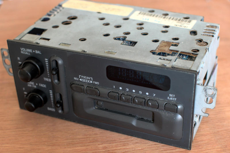
One goal was/is to reuse the old case of my cassette radio, including buttons a.s.o.
The original plan was to use the various analog inputs of the ESP32 as well as digital ones for buttons.
I'm reusing some of the circuit boards behind the elements, so I'm stuck with their wiring. No big issue.
In the place of the original 7-segment display plus a few indicators, I was able to mount the 0,9" 128x32 Pixel OLED.
Enough real estate for displaying stuff.
But what I didn't know at the time, the ADC of the ESP32 are terrible. Lots of noise (stable analog voltage), but the read values jump all over the place. Not only drifts, but big jumps. This made it unusable.
So 2x ADS1115 to the rescue. With a little resistor-ladder-magic I was able to convert all inputs into 8 analog signals read through the ADS1115 modules into the µC via I²C. Clean and stable value (if powered by a good voltage source).
This brings us to the final issue in this article.
Noise
After getting the TEF6686 module to run and the basic IO with the buttons and the first graphics on screen I noticed audible noise in the FM module on I²C activity. Annoying noise, every screen update or input polling created a tick sound. I tried various shielded cables for the I²C connections, used a dedicated I²C port for the FM module a.s.o. Nothing fixed it. Even after powering the FM module from a dedicated power source (but with common ground because of I²C), the tick was there.
Running out of ideas triggered me to galvanically isolate the UI from the other parts, since this caused the noise.
I found a DC-DC module with input/output isolation and wide input range (9-18V) and stable 5V output, a CINCON EC3A11.
This powers an Arduino Nano that does the input polling and driving of the display and read/writes to a serial port. This is also galvanically isolated via 2 opto-couplers (LTV817, I chose those, because I had them). Since the opto-couplers are not the fastest, I'm only using 4800 baud. 9600 Baud was a bit unstable. Again take a look at the data sheet, the speed depends on the load the opto-coupler has to drive. Using the internal pull-ups from the ESP32 was too weak, I had to add an extra 1k pullup in parallel to increase the current and the speed. On the Arduino side it was not an issue, it drives with 5V and a lower pull-up resistor. And for my few byte serial communication, 4800 Baud is plenty fast.
I'm only sending from front to controller when the user pressed a button or turned a knob. This is a 4 byte message and update from the controller to the display, for example a RDS update or time change. Also just a few bytes.
The separation has also the benefit, that the project is easier to adapt to other UIs/Buttons/whatever.
Current status
This is the current status for now, the UI interface works and can send/receive updates and does not create audible noise in the FM-Modules, Bluetooth looks fine, the audio mixing works and left/right front/back post-processing works.
The software needs to be optimized next, not everything is supported yet, except hardcoded things. The schematics and PCB designs are up to date with all fixes (and differ from the build/hacked ones), but I might need to make more changes. Only time will tell.
As soon as I'm confident that no big oopsie are left, the plans and source code will be published here.